News Release – For Immediate Release
United Electric Controls Introduces TX200H HART® 7 Smart Pressure Transmitter
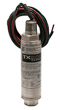
United Electric Controls introduces the TX200H, a HART® smart pressure transmitter designed for upstream oil and gas applications. The TX200H provides simplified field adjustment while reliably communicating asset management data utilizing the latest HART®7 specification.
A flexible 10:1 turndown on pressure ranges from 0 to 15 psi (0 to 1 bar) up to 0 to 25,000 psi (0 to 1724 bar) allow users to range the transmitter as application requirements change while reducing inventory levels through model reduction. The TX200H real-time diagnostics also reduce maintenance costs by reporting device health status and process performance, alerting users to potential problems to troubleshoot before escalation occurs.
The TX200H is constructed of 316 stainless steel, welded and hermetically sealed to meet enclosure type 4X and IP66 requirements. Its rugged design lends itself to being mounted directly onto the process or panel mounted within the control panel. Standard approvals include cULus for Class 1, Div. 1 & 2, Zone 1 and ATEX Ex d and Ex tD hazardous areas. It is CE compliant to both PED and EMC directives.
Integrating the TX200H into most process systems is simple. Since HART® communication is superimposed over the 4-20 mA signal, the TX200H can use existing wiring as an upgraded, drop-in replacement for a standard analog 4-20 mA transmitter. A user may easily communicate with the TX200H utilizing a handheld device or a PC equipped with commercially available software.
About United Electric Controls:
In business since 1931, United Electric Controls is a privately held corporation headquartered in Watertown, MA. It manufactures durable and reliable pressure, temperature and flow switches, controls, transducers and sensors. Providing protection to equipment, processes and personnel in a variety of industries, UE products range from simple units to highly specialized custom designs. For more information about any of its offerings go to http://www.ueonline.com/. or Call Glen Doole at 905-464-2605.
Thursday, June 23, 2011
Tuesday, May 17, 2011
News Release – For Immediate Release
United Electric Controls Introduces TX200H HART® 7 Smart Pressure Transmitter
United Electric Controls introduces the TX200H, a HART® smart pressure transmitter designed for upstream oil and gas applications. The TX200H provides simplified field adjustment while reliably communicating asset management data utilizing the latest HART®7 specification.
A flexible 10:1 turndown on pressure ranges from 0 to 15 psi (0 to 1 bar) up to 0 to 25,000 psi (0 to 1724 bar) allow users to range the transmitter as application requirements change while reducing inventory levels through model reduction. The TX200H real-time diagnostics also reduce maintenance costs by reporting device health status and process performance, alerting users to potential problems to troubleshoot before escalation occurs.
The TX200H is constructed of 316 stainless steel, welded and hermetically sealed to meet enclosure type 4X and IP66 requirements. Its rugged design lends itself to being mounted directly onto the process or panel mounted within the control panel. Standard approvals include cULus for Class 1, Div. 1 & 2, Zone 1 and ATEX Ex d and Ex tD hazardous areas. It is CE compliant to both PED and EMC directives.
Integrating the TX200H into most process systems is simple. Since HART® communication is superimposed over the 4-20 mA signal, the TX200H can use existing wiring as an upgraded, drop-in replacement for a standard analog 4-20 mA transmitter. A user may easily communicate with the TX200H utilizing a handheld device or a PC equipped with commercially available software.
About United Electric Controls:
In business since 1931, United Electric Controls is a privately held corporation headquartered in Watertown, MA. It manufactures durable and reliable pressure, temperature and flow switches, controls, transducers and sensors. Providing protection to equipment, processes and personnel in a variety of industries, UE products range from simple units to highly specialized custom designs. For more information about any of its offerings go to http://www.ueonline.com/.
If you want more information about this product please contact me at my office at 1-800-313-3103.
Glen Doole
Senior Technical Sales Representative (Instrumentation)
Tuesday, July 20, 2010
Jerguson Solutions
Ammonia Refrigeration Level Measurement
Application Issue:
Major frozen food producers utilize ammonia and/or CO2 liquids for refrigeration and flash-freeze system management. Existing level indication on these systems is typically a long column with several small bulls-eye sight windows or, in some rare cases, an armored glass level gage, such as a Jerguson Series 20.
There are two drawbacks to the column and bulls-eye window approach. First, the bulls-eye windows are spaced at about one-foot increments , making an accurate level verification virtually impossible. Second, due to the material of the glass used in these bulls-eye units, erosion can lead to catastrophic failures resulting in down time of the refrigeration system, lost production time on the freezer units, or, more importantly, possible harm to personnel.
Remote level monitoring of this system is typically accomplished through the use of a capacitance probe inserted into the top of the level column. Since oil can accumulate in this system, that oil can foul the capacitance transmitter and lead to a false level indication. If a capacitance transmitter needs to be replaced, the column must be isolated since the transmitter is in contact with the process.
An ammonia refrigeration system typically operates at temperatures in the range of -20°F to -80°F. While ammonia in the vessel may be very stable at a temperature of -20°F to -80°F, due to the vapor pressure of the system, temperature differences between the fluid in the vessel and gage column can cause flashing of ammonia in the gage column.
Jerguson® Solution
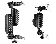
The new Jerguson FlashProof Magnicator II with a magnetostrictive transmitter addresses the concerns with traditional level controls in ammonia and/or CO2 refrigeration to provide reliable level indication and control. The FlashProof Magnicator II delivers the same reliable performance demanded of Jerguson’s Magnetic Level Gage, and the oversized 3” chamber with internal guides permits any entrained vapors due to boiling to harmlessly pass behind the float. The use of a Magnetic Level Gage in this application also allows easy level verification over the entire operating range, as opposed to guessing at a level by looking through portholes. The externally-mounted Magnetostrictive transmitter sends a continuous 4-20mA signal to the customer’s instrument panel for level control and is not affected by oils in the process.
Jerguson® Solution
The new Jerguson FlashProof Magnicator II with a magnetostrictive transmitter addresses the concerns with traditional level controls in ammonia and/or CO2 refrigeration to provide reliable level indication and control. The FlashProof Magnicator II delivers the same reliable performance demanded of Jerguson’s Magnetic Level Gage, and the oversized 3” chamber with internal guides permits any entrained vapors due to boiling to harmlessly pass behind the float. The use of a Magnetic Level Gage in this application also allows easy level verification over the entire operating range, as opposed to guessing at a level by looking through portholes. The externally-mounted Magnetostrictive transmitter sends a continuous 4-20mA signal to the customer’s instrument panel for level control and is not affected by oils in the process.
Due to the cryogenic temperatures in this application, the Non-Frost Extension option must be selected to facilitate insulation. (Field installation of the insulation eliminates the potential for damage during transit and installation.)
Contact Glen Doole at Peacock your Canadian Jerguson Representative for additional information!
Tuesday, June 22, 2010
Open Channel Flowmeters
How Open Channel Flowmeters Work
Open channel flowmeters measure the flow of liquids that are open to the atmosphere at some point in the measurement system. The liquid may be entirely open to the atmosphere, or may be contained within a closed pipe that is not full of liquid and only open to the atmosphere at the flowmeter itself.
Open channel flowmeters generally consist of a primary device, transducer, and transmitter. The wetted primary device restricts the liquid flow stream. Under flowing conditions, this restriction causes a rise in liquid level at a location either upstream or within the flowmeter. When the flow increases, the level rises higher. A transducer is mounted on or near the primary device to sense the level. The electronic transmitter uses the signal from the transducer to measure the level to determine liquid flow.
Different geometries are used for open channel measurement, including flumes that make the channel narrower, weirs that force the liquid over a dam-like obstruction, and nozzles that restrict the flow of liquid before it freefalls from the nozzle.
How to Use Open Channel Flowmeters
Open channel flowmeters measure the flow of liquids that can be safely exposed to the atmosphere, such as water and sewage. Applications for these flowmeters are primarily found in the water and wastewater industries to measure water and sewage flows. However, there are usually a few applications for open channel flowmeters to measure effluent flows in the mining, mineral processing, power, pulp and paper, petroleum, chemical, and petrochemical industries. Due to the limited applicability of open channel flowmeters, materials of construction are typically limited to those that target these applications. Sizes range from a few inches to tens of feet. It is generally less expensive to purchase smaller open channel flowmeters and field construct larger ones (typically with concrete).
Application Cautions for Open Channel Flowmeters
Open channel flowmeters pose potential environmental and safety issues because the liquid is exposed to the environment. Also, dirt can accumulate and plug the sensing systems of some designs. Dirt can also adversely affect the accuracy of these flowmeters.
A straight run of channel is usually installed upstream of the primary device to condition the flow to be free of jetting and eddies. The channel should properly mate with the flowmeter and not create any abrupt dimensional changes at the transition. Be careful when designing the channel downstream of the flowmeter because some open channel flowmeters require free-fall conditions, whereas others require a downstream channel.
When installing the primary device, be sure to level the flowmeter per manufacturer specification in all planes. Make sure that the transducer is mounted in the correct location because failure to do so can cause erroneous flow measurements.
Tuesday, June 1, 2010
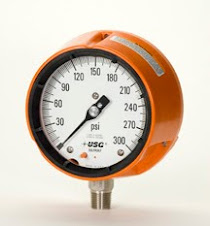
Pressure Gauges being a very simple device have some complexities.
To address these complexities Ron Williams at Ametek US Gauge
To address these complexities Ron Williams at Ametek US Gauge
has written the following white paper on Ametek US Gauge,
I hope you find it interesting.
SUPERIORITY OF SEAMLESS
BOURDON TUBE IN PRESSURE
GAUGE APPLICATION
By Ron Williams, Sr. Design Engineer, PE &
Gordon Sun, Product Manager, CQE/CQM
An AMETEK US Gauge White Paper
Introduction
Pressure tubing requires an uncompromising level of quality
because of the critical end-use applications. In petrochemical
and refining facilities often there are presences of highly
corrosive and even lethal process media being produced,
processed, or transported. Because of severe environmental
impact in case of potential rupture, tubes and pipes are
almost always specified to be seamless to offer the highest
level of assurance of safety.
At AMETEK U.S. Gauge we consider the Bourdon Tube an
integral part of the piping and tubing system. Therefore, if
specification requires pipes and tubes to be seamless, then
why would you consider anything else but U.S. Gauge, the
only process gauge brand manufactured with seamless
Bourdon Tube in the marketplace?
Weakness of Welded Bourdon Tube Design Due to economic
reasons, the majority of pressure gauge manufacturers use
welded tubing to form into Bourdon Tube...
1.Even if manufactured to strict production standards
and procedures that allow these welded tubing to meet the
precise ASTM/ASME specifications required for pressure
vessels, there are still numerous disadvantages inherent in
the welded Bourdon Tubes. Among these key disadvantages
are
and procedures that allow these welded tubing to meet the
precise ASTM/ASME specifications required for pressure
vessels, there are still numerous disadvantages inherent in
the welded Bourdon Tubes. Among these key disadvantages
are
1) welding heat-affected zones,
2) susceptibility to crevice corrosion,
3) non-homogeneity in grain structures,
4) costly testing to ensure weld integrity, and
5) careful orientation of weld seam away from high stress areas.
It is for these reasons that the ANSI/ASME codes derate the
strength of welded tube to 85% that of seamless tube
strength of welded tube to 85% that of seamless tube
2.The codes provide that welded tube rated equal to the strength of
seamless tube must be 100% radiographically inspected.
1 Based on AMETEK USG competitive benchmarking research
seamless tube must be 100% radiographically inspected.
1 Based on AMETEK USG competitive benchmarking research
conducted in 2005
2 ANSI/ASME Boiler and Pressure Vessel Code, Section VIII,
2 ANSI/ASME Boiler and Pressure Vessel Code, Section VIII,
Division I, Table UHA-23, Page 162
AMETEK USG Advantage
AMETEK USG has over 100-years of experience of
manufacturing Bourdon Tubes and pressure gauges, and
understands that the “heart” of a pressure gauge is its
Bourdon Tube. This is the reason USG uncompromisingly
AMETEK USG has over 100-years of experience of
manufacturing Bourdon Tubes and pressure gauges, and
understands that the “heart” of a pressure gauge is its
Bourdon Tube. This is the reason USG uncompromisingly
stayed with the seamless Bourdon Tube design even as
stainless steel raw material cost is ever increasing. There
is no substitution for safety. Seamless Bourdon Tube offers
numerous advantages that make it superior to our competition.
Advantage 1
Seamless Bourdon Tube is without heat-affected zone.
The welded tube heat-affected zone possesses an altered
metallurgy to that of the base metal. The welding process
can transform the local microstructure increasing grain size
when heated and producing stresses between the heat
effected zone and the base metal that promote cracks on
cooling.
Advantage 2
Seamless Bourdon Tube has superior resistance to
corrosion. An incomplete welding process, however minute
can leave microscopic gaps that provide entry for corrosive
contaminates and stress risers that in time could lead to the
failure of the weld seam. This is also known as crevice corrosion.
Crevice corrosion is the result of the accumulation of foreign
material in crevices that are created on the surface of the
stainless steel component. Among the different kinds of
corrosion that stainless steel can be susceptible to, crevice
corrosion is one of the most common types, which usually
occurs in joints, cavities, holes, grooves, gaskets, and gaps of
any stainless components. Conditions that cause stainless
crevice corrosion, (including very high temperatures) can
totally degrade the entire surface of the stainless steel
component, which in turn would make the steel vulnerable to
oxidation or rusting.
Advantage 3
Seamless Bourdon Tube has homogeneous grain
structure. Welded tube requires a secondary localized cold
work applied to the weld seam (bead working). Cold working
imparts homogeneity to the grain structure improving
corrosion resistance. Improper bead working can lead to
uneven cold work, discontinuities or laps causing premature
failure at the weld. For seamless Bourdon Tube there is no
need for this secondary process to homogenize irregular postwelding
grain structure.
Advantage 4
Seamless Bourdon Tube does not require costly tests
to ensure weld integrity. Where safety and reliability is of
paramount concern because of high pressures or hazardous
materials, it is recommended that the tube receive additional
non-destructive examination to ensure the weld integrity.
Seamless Bourdon Tube offers the superior security and
assurance because there is no weld integrity to concern
about.
Advantage 5
Seamless Bourdon Tube does not require difficult
weld seam orientation in pressure gauge
manufacturing processes. In applications such as a
Bourdon Tube, the weld seam must be located and marked
prior to any additional cold work to prevent the seam from
being located in a highly stressed area during tube flattening
and coiling. If improperly done the weld might be subjected
to stresses approaching yield. Any microscopic imperfections
may produce stress concentrations in excess of its strength
limits, making it susceptible to corrosion.
In almost all cases, the welded seam is visually
indistinguishable after polishing and successive drawing
operations, making the task of properly aligning and
orienting virtually impossible when forming and coiling the
Bourdon Tube.
Advantage 6
Seamless Bourdon Tube does not require pressure
derating or secondary inspection for hazardous and
critical applications. It is for reasons cited above that the
ANSI/ASME codes derate the strength of welded tube to 85%
that of seamless tube. With the seamless Bourdon Tube
design, AMETEK USG process gauges have the highest
overall tested and published burst pressures in the industry.
Summary
What is the cost of a hazardous material spillage and its
clean up? What is the cost of shutting down and starting up
a process? What is the cost of negative publicity on the 6
o’clock evening news? What is the cost to environmental
impact? AMETEK USG understands that there is always an
eventual price to pay for using inferior product.
The best advantage of all? AMETEK USG process gauges,
with the Seamless Bourdon Tube, are price competitive with
“lesser” process gauges. You are getting superior reliability
and performance for free!
Test data, based on actual minimum rupture pressures observed,
available from AMETEK USG upon request. The best advantage
of all? … you are getting superior reliability and performance for
FREE!
USG Process Gauges are Proudly Made in the U.S.A.
of all? … you are getting superior reliability and performance for
FREE!
USG Process Gauges are Proudly Made in the U.S.A.
Thursday, April 29, 2010
Using Correct Conductivity Temperature Compensation
This article was written by Lori L. McPherson.
When this article was written Lori L. McPherson, B.S. Chem E., was the analytical Specialist for Georg Fischer, Inc., Tustin, California.
When this article was written Lori L. McPherson, B.S. Chem E., was the analytical Specialist for Georg Fischer, Inc., Tustin, California.
Conductivity measurements are normally used to interpret the quantity of ions contained in the solution. The temperature of the solution can have a large effect on the reading. Most conductivty instruments will "Compensate" for this conductivty affect, allowing the reading to be standardized to an estimated value at 25 deg. 'C'. For water solutions, a temperature compensation factor, or coefficient of 2 percent per degree celtigrade, is normally used. This compensation is reasonably accurate on the conductivity measurement. However, in solutions other than water the actual coefficient ma be significantly different, and if not programmed correctly can result in a very large measurement errors.
The Conductivity Measurement
The conductivity measurement is literally a measure ment of of the solution's ability to conduct electricity. It is directly affected by the number of disolved ions in the solution. As the number of disolved ions increases, the ability to conduct electricity also increases. The measurement Value is generally considered to be a measurement of the actual number of ions contained in the sample, while in fact, this is only inferred.
The conductivuty measurement measurement unit is the inverse of the resistivity measurement. Resistivity measures the solution's ability to resist electrical current flow.This is measured in Ohm*cm. Therefore, conductivity mhos/cm, with mhos being defined as Ohms-1. This unit has been renamed by the international standards organization to be Siemen (S). However, both mhos/cm and S/cm are considered correct. In clean water (surface water, well water, etc.), the order of magnitude is in the range of 10-6 S/cm or uS/cm. ( us/cm = micro seimens).
The Affect of Temperature on Conductivity
The solution's ability to conduct electricity is related to the concentrationnand specific conductivity of the ions in the solution, and the temperature of the solution. Increased temperature provides increased activity or ionic movement that enables more electricity to be carried through the solution from one electrode to another.
In order to better correlate the electrical conductivity to the concentration of ions, the affect of temperature on the solutions ability to conduct electricity is subtracted from the actual conductivity. For example, a solution at 25 deg 'C' may conduct 200 uS. This same solution at 35 deg 'C' would conduct 240 uS. Since the primary purpose of the measurement is to correlate to the purity of the solution, the affect of temperature is subtracted (compensated), with a displayed, compensated value shown at 200 uS. This provides a means of standardizing the conductivity reading to a concentrationof ions at 25 deg 'C'.
Applications with Coefficients Different from Water
Many solutions other than water are effectively controlled using conductivity. Some of these include offset printing fountain solutions, water soluble lubricants used in metal machining and quenching solutions. many of these solutions have been tested to determine their temperature coefficients, and have been found to have coefficients significantly different than the 2.0 perecnt per degree celcius used for water solutions. If the coefficient used is incorrect, when the temperature of the solutions change, the conductivity value will be seen to change. However, in reality, the concentration in the solution remains the same.
Other solutions, such as acids or bases, can also have temperature coefficients significantly different than that of water. In many cases, each concentration range of a solution will have it's own temperature coefficient. For example, 10 percent sulfuric acid will have a muuch diufferent temperature coefficient than 50 percent, and those values will be different than sulfuric acid at 90 percent. To maintain the highest level of accuracy across temperature changes, it is recommended to check the temperature response of the solution, and program the instrument accordingly.
Applications that Should Not be Temperature Compensated
In some applications, the measurement of the true or actual electrical conductivity is important, without any standardization back to the conductivity level at 25 deg. 'C'. One example of this type of application is the salt solution used to shock poultry prior to processing. The salt content of this solution is monitored using conductivity, to ensure that it can carry sufficient current to effectively stun the chicken. In this case, the temperature compensation program should be deactivated (generally by introducing a coefficient of 0.0 per degree celcius). This activity guarantee that thsi measurement is a true measurement of the electrical current the solution will pass, and the process will operate as needed.
A second example is the reionization of pure water to prevent carona discharge across high pressure nozzles.In the semiconductor industry, the water used in rinsing wafers must be free of any impurities. In thuis state, the water generally has a resistivity associated with it of 18.3 Mega Ohms. Unfortunately, water this resistive can cause a static, or corona discharge when the water passes through a high pressure spray nozzle. This discharge, or sparking, can badly damage the wafer being washed. By re-ionizing the water with carbon dioxide, the water regains some ability to conduct electricity, without salt contamination, and the discharge is prevented. In this case, the electrical property of the solution is the important property, not it's inference to the content of carbon dioxide. Therefore, temperature compensation should not be used for optimum process control.
Determining the Temperature Coefficient
For many chemicals, the temperature coefficient may be obtained from published data such as that found in "Dobo's Electrochemical Data" . If the data is not available, it can be determined experimentally quite easily.
It is important to realize that the function of temperaturecompensation is to normalize the reading back to that which would occur at 25 deg.'C'. This is the referencepoint for the determination of the temperature coefficient. In other words, the coefficient defines the change in conductivity per each degree celcius change in temperature, from the reference or starting point of 25 deg. 'C'. Using water as an example, with a 2 percent per degree celcius coefficient (TC=0.02), the coefficient defines the conductivity increase as 2 percent of the reading at 25 deg. 'C'. A 1000 uS solution at 25 deg 'C' would increase 20 uS in conductivity with each one degree celcius temperature change.If the temperature range is 40 to 50 deg. 'C', the relationship to temperature must be linearized back to give a conductivity readingat 25 deg. 'C' to eastablish a correct temperature coefficient. This is the basis for the calculation below for determining the coefficient from the conductivity values at two different temperatures:
C1 = C25 * (1+(TC*(T1-25))
Using two data points at temperatures other than 25 deg. 'C' (for ease of experimentation), and solving the two equations for C25, enables the determination of the TC to be simplified to the following equation:
TC = (C1-C2) / C2 (T1-25) - C1 (T2-25)
Where C25 is the conductivity (reference) at 25 deg 'C', C1 is the conductivity at temperature T1, and C2 is the conductivity at temperature T2.
When obtaining values for C1 (@T1) and C2 (@T2), it is critical to disable any tremperature compensation in the instrument. this is normally accomplished by setting the coefficient to 0.0 percent per degree 'C'.Once this has been done, the readings taken at the two temperatures will be raw conductivity values, and can be used in the calculation. It is recommended that the two points used represent the maximum range of temperature for the application being tested. Furthermore, allowing time for the temperature to stabilize, and taking several readings for statistical averaging will greatly increase the accuracy of thsi determination.
Non-Linear Temperature Compensation
In some situations, temperature compensation does not follow a clean, linear relationship as defined above. The most common of these applications is pure water, in the resistivity range of 1 to 18.3 Mega Ohms * cm. For this application, resistivity instruments are pre-programme for the exponential response to temperature that can occur. A linear compensation program would be highly inaccurate for thisapplication, especially i temperatures below 25 deg. 'C'
Wednesday, April 14, 2010
A Simple Test Could Save Your Life ! ! !
A Simple Test Could Save Your Life
Written by: William Ball
If you use a personal safety gas monitor in your job, you need to be aware that taking a few seconds to perform a "Bump Test" every day could mean the difference between going home to your family at the end of the workday and becoming another industrial workplace fatality
The "National Institute for Occupational Safety and Health (NIOSH) estimate millions of workers globally may be exposed to hazards in confined spaces, and every year a large number of those workers become workplace fatality statistics. Those killed include not only the individuals working in the confined space, but frequently those who attempt to rescue them. Confined spaces are encountered in a wide variety of industries including:
• Mining
• Construction
• Water and sewer operations
• Oil and Gas, Petrochemical
• Shipping vessel and aircraft maintenance
Sewers, underground cable vaults, tanks/vessels, silos, and aircraft wings are easily identified as confined spaces. Others may not be so obvious, for example opened topped chambers, vats, manure pits, unventilated or poorly ventilated rooms.
Global confined space statistics show that the Majority of confined space fatalities result from hazardous atmospheric conditions. In Australia it is estimated that in 75% of confined space accidents the atmosphere was not tested prior to entry. The lack of proper training and understanding the inherent hazards are the key contributing factors to confined space accidents. Awareness of potential hazards is essential to any confined space safety program and testing the atmosphere wit an appropriate, properly functioning, safety gas detector is the only way to determine whether it is safe to enter.
After a confined space has been cleared for entry it is essential to monitor continuously while workers occupy the space. Atmospheric conditions can change without warning ! Work activities in confined spaces such as welding, painting and degreasing, to name a few, can produce dangerous atmospheric conditions. Atmospheric hazards can also come from sources outside of the confined space. Many atmospheric gas hazards are colourless and odourless so monitoring with an appropriate safet gas detector is essential to protecting workers.
Everyday workers around the world trust their portable safety gas detectors to warn them of possible life threatening atmospheric gas hazards, often with little understanding of how these important pieces of safety equipment work. Serious injury or death can be caused by exposure to toxic gases, oxygen deficient environments or explosions caused by the combustible gases.
Why is “Bump Testing” Necessary ?
Portable gas detectors can contain various types of sensor technologies with different detection principles. The most common configuration in a confined space entry gas detector includes sensors for the detection of Oxygen concentration and the presence of Hydrogen Sulphide, carbon monoxide and combustible gases. Workplace environments can be harsh and gas detectors are subjected to all kinds of conditions that can and do affect their operation. Instruments can be physically damaged, sensor ports can become obstructed by dirts and oils, sensors can be damaged by exposure to gas concentrations that exceed their detectable limit, and sensors can be exposed to compounds in the atmosphere tha can degrade their performance.
The catalytic hot bead combustible sensor used in many safety gas detectors is particularly prone to damage by compounds that can be encountered daily in the workplace environment. This type of combustible gas sensor contains two coils of very fine platinum wire coated with ceramic or porous alumina material to form refractory beads. The beads are connected to opposing arms of a balanced Wheatstone Bridge Electrical Circuit. One bead (Active) is additionally coated with Platinum or Palladium, which enables catalytic oxidation of combustible gases at concentrations below the Lower Explosive Level (LEL) to occur. The opposing bead (Reference) is identical in structure except it has been poisoned so that the catalytic oxidation cannot occur. Both beads are heated to specific temperature and in normal air, the wheatstone bridge circuit remains balanced. If combustion gas is present, catalytic oxidation will heat the active bead to a higher temperature than the opposing reference bead, unbalancing the electrical resistance in the wheatstone bridge. The difference in the electrical resistance of the active bead versus the reference is proportional to the concentration of the combustible gas in the atmosphere.
One of the limitations of this catalytic bead technology is that the sensor is potentially prone to damage through exposure to airborne contaminants capable of impairing sensor performance, or permanently destroying the sensor. Some airborne substances can decompose on the active sensor bead catalyst and form a solid barrier over the catalyst bead surface, effectively poisoning the sensor. Silicone vapours are the most commonly encountered workplace substance capable of destroying catalytic bead sensors. Many commercially available lubricants, rust inhibitors, adhesives and cleaners contain silicone based compounds. Some other poisons to be aware of are compounds containing lead, Sulphur or phosphates and high concentrations of combustible gases. A single exposure to a high concentration of a sensor poison can destroy the catalytic bead combustible sensor, or sensors can lose sensitivity gradually as a result of chronic exposure to contaminants.
Halogenated compounds such as chlorinated hydrocarbons and chlorofluorocarbons are absorbed by the active sensor catalyst inhibiting the sensor response. Exposure to these compounds is typically temporary and once the detector is removed from the contaminated environment the sensor will recover normal sensitivity. In some cases, chronic exposure to inhibitors will permanently damage the catalytic bead combustible sensor.
Electrochemical sensors used for the detection of toxic gases such as carbon monoxide and hydrogen Sulphide are not as prone to poisons as the catalytic bead sensor, but their performance can also be compromised by certain ambient contaminants. Many electrochemical sensors can be temporarily or sometimes permanently damaged by exposure to organic solvents and alcohols. Methanol, which is one widely used in many parts of the world during the cold winter months, can have a profound effect on CO and H2S sensors. Many insect repellants contain alcohol and use hydrocarbons such as propane or butane as an aerosol propellant. Both can affect gas detector sensors. High concentrations of solvents can also affect internal components of the electrochemical toxic and oxygen sensors resulting in permanent damage.
Unfortunately , even though the gas detector performs diagnostic checks at start up and during operation, it is often not possible to electronically detect a problem with sensor response. The detector cannot warn users that the sensor ports are obstructed by dirt, oil or some other substance. or that the capillary pore of an oxygen sensor is blocked, or that the catalytic bead of a combustible sensor has been poisoned. A personal safety gas detector cannot properly protect a worker if gas molecules cannot get into the sensor or if the sensor’s ability to detect the target gas has been compromised.
The only way to confirm that a gas detector is functioning, and is capable of responding to gas, is to expose the instrument to a concentration of target gas high enough to initiate an alarm situation while the instrument is in operating mode. This procedure is often referred to as performing a “Bump Test” and is key to the safe use of portable safety gas detection equipment.
How often should I bump test or calibrate?
At minimum follow the safety gas detector manufacturer’s recommendations for bump testing and calibration frequency. Additional testing of a gas detector should also be performed if a detector has been subjected to any of the following circumstances:
1. Chronic exposure to, or used in, extreme environmental conditions, such as high/low temperature and humidity, and high levels of airborne particulates.
2. Exposure to hi (over range) concentrations of the target gases or vapours.
3. Chronic or acute exposure of catalytic “Hot-Bead” LEL sensors to poisons and inhibitors. These include:
• Volatile Silicones
• Hydride Gases
• Halogenated Hydrocarbons
• Sulfide Gases
4. Chronic or acute exposure of electrochemical toxic sensors to:
• Alcohols
• Solvent Vapours
• Highly corrosive Gases
5. Harsh Storage and operating conditions, such as when a portable gas monitor is dropped onto a hard surface or submerged in liquid. Normal handling/jostling of the monitors can create enough vibration and or shock over time to affect electronic components and circuitry.
6. Change in custody of a monitor.
7. Change in work conditions that might have an adverse effect on sensors.
8. Any other conditions that would potentially affect the performance of the monitor.
Bump Testing has to be a part of any safety program !
In the evolution of safety gas detection instrumentation “Bump Testing” is a relatively new practice. Calibration of gas detection equipment is part of routine maintenance. There was a time when manufacturers recommended frequent, even daily calibration, but as sensor technology and sensor performance became better understood, the frequency of calibration lengthened. As calibration frequency decreased it was just assumed that the detector was operating properly between calibration intervals. Today, although recommended calibration frequency may vary considerably from one safety gas detector manufacturer to the next, there is unanimous agreement amongst manufacturers that it is necessary to bump test detectors between calibrations. Again, there is no manufacturer consistency in the wording of the Bump Testing recommendation found in gas detector manuals. Gas detector users cannot be blamed if they are confused and do not understand why Bump Testing is necessary. As a result the practice is often not adopted and in some areas of the world Bump Testing personal gas detectors between calibration intervals is virtually unheard of.
The concept of a Bump Test I to verify the detector sensors respond to a target gas and that the detector alarms activate. This is sufficient for many users, but others perform a calibration check, confirming the accuracy of the sensor response while testing.
Sensor Calibration adjusts response accuracy and Bump Testing verifies sensor response between calibration intervals. Performing a Bump Test takes only seconds and provided gas detection users with confidence that the detector about to be used is working. Be sure to use test gas for a reliable source, and check the expiry date on the cylinder. If a detector does not pass the Bump Test protocol do not use it. Additional testing should be done to diagnose the cause.
With the development of automated Calibration and Bump Test systems, the process can be as easy as pushing a button. Many automated systems keep a permanent record of each test performed so that in the event of an accident investigation detailed proof of proper maintenance and testing can easily be produced. Records of manual Calibration and Bump Testing must also be kept. Remember if it wasn’t recorded, it wasn’t done!
Increased safety awareness and improved safety practices do make a difference. According to the U.S. Department of Labour, Industrial fatalities in 2006 were at the lowest rate since the fatality census began in 1992. In 1992 the number of fatal work injuries per 100,000 workers was 5.2; In 2006 the figure was down to 3.9. In Britain the same trend in workplace fatalities is evident. Since the introduction of the health and safety at work act an 1974 work related deaths have decreased approximately 35%. In 2005/2006 the number of fatalities was at the lowest level ever recorded. Fewer fatalities are the result of increased awareness and improved safety practices.
Most confined space deaths that result from exposure to lethal atmospheric conditions could have been prevented . Implement an effective confined space entry program and appropriate safety equipment . Most atmospheric gas hazards are imperceptible to human senses, so testing the atmosphere prior to entry and continually monitoring for changes in conditions using a properly working personal safety gas detectors is essential to keeping workers safe. As a minimum requirement, Bump Testing a safety gas detector prior to each days use should be a part of any effective confined space entry safety program.
Author Details:
William Ball
Product Applications and Training Specialist
Honeywell Life Safety
BW Technologies by Honeywell
2840 – 2 Avenue SE
Calgary, Alberta
T2A 7X9
www.gasmonitors.com
Subscribe to:
Posts (Atom)